<Raspberry Pi-44>
LCD(AQM0802A)の表示は、Raspberry Pi-23からRaspberry Pi-32で、紹介しましたがプログラムは
シェルスクリプトでした。
今回は、Python3を使って文字表示させたいと思います。LCDは、AQM0802A(8文字/1行の2行タイプ)と
AQM1602(16文字/1行の2行タイプ)を使います。
プログラムは、書籍の「RaspberryPiで学ぶ電子工作」を参考にしました。
尚、O.Sは2017-04-10-raspbian-jessie.imgを使用しました。
<AQM0802A>
回路図はRaspberry Pi-23を参照してください。
<ポイント>
LCDの資料を見ると、LCDに送るデータはインストラクションコード(例ディスプレイクリア命令などの制御)を
送る場合と液晶の表示データ、CGRAMデータを送る2通りあるようです。
そして、この2通りのデータを選択するには、コントロールバイト(control byte)が関係していて
次のように記載されています。
<コントロールバイト(control byte)>
MSB LSB
8 7 6 5 4 3 2 1 ビット
C R 0 0 0 0 0 0
↑
ここ(7ビット目)
注 C:Co R:RS の略
*7ビット目のRSが0(0x00)なら制御コードの命令になる、1(0x40)ならデータを書き込む命令になる
0000 0000 (0x00) 制御コードの命令
0100 0000 (0x40) データを書き込む命令
<Pythonで記述する>
例 ディスプレイクリア(ClearDisplay 0x01)する場合
smbus.SMBus(1).write_byte_data(0x3e,0x00,0x01) → 0x3e:i2cアドレス 0x00:control byte 0x01:ClearDisplay
例 表示データ A(0x41)を書き込む場合
smbus.SMBus(1).write_byte_data(0x3e,0x40,0x41) → 0x3e:i2cアドレス 0x40:control byte 0x41:A
上記は、1文字の書込みですが複数文字連続の書込みは下記のようにします。
smbus.SMBus(1).write_i2c_block_data(0x3e,0x40,[0x31,0x32,0x33]) (123と表示する)
-------------------- ----------------
write_byte_data→write_i2c_block_dataにする、[ ]の中に文字データを書く。
ABCDEFGHの表示(下の"少し発展させたABCDEFGH表示のプログラム"を実行)
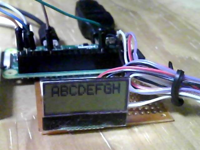 LCDの文字表示は、最初にLCDの初期化をした後、表示文字をASCコードに変換したデータをLCDに書き込みます。
例えば、"A"なら0x41、LCD資料のキャラクターパターン参照(0x00-0xFF)
<LCDの初期化 データーシートから>
①Functionset(0x38)
>27μs待つ
↓
②Functionset(0x39)
>27μs待つ
↓
③Internal OSC frequency(0x14)
>27μs待つ
↓
④Contrastset(0x70)
>27μs待つ
↓
⑤Power/ICON/Contrastcontrol(0x56)
>27μs待つ
↓
⑥Follower control(0x6c)
>200ms待つ
↓
⑦Functionset(0x39)
>27μs待つ
↓
⑧Clear Display(0x01)
>27μs待つ
↓
⑨Clear Display ON/OFF control(0x0c)
>27μs待つ
<python3でAを表示するプログラムの基本>
-----------------------------------------------------------
import smbus
from time import sleep
#*****lcd初期化*****
smbus.SMBus(1).write_byte_data(0x3e, 0x00, 0x38) #①
sleep(0.0001)
smbus.SMBus(1).write_byte_data(0x3e, 0x00, 0x39) #②
sleep(0.0001)
smbus.SMBus(1).write_byte_data(0x3e, 0x00, 0x14) #③
sleep(0.0001)
smbus.SMBus(1).write_byte_data(0x3e, 0x00, 0x70) #④
sleep(0.0001)
smbus.SMBus(1).write_byte_data(0x3e, 0x00, 0x56) #⑤
sleep(0.0001)
smbus.SMBus(1).write_byte_data(0x3e, 0x00, 0x6c) #⑥
sleep(0.2)
smbus.SMBus(1).write_byte_data(0x3e, 0x00, 0x38) #⑦
sleep(0.0001)
smbus.SMBus(1).write_byte_data(0x3e, 0x00, 0x0c) #⑧
sleep(0.0001)
smbus.SMBus(1).write_byte_data(0x3e, 0x00, 0x01) #⑨
sleep(0.0001)
sleep(1) #lcd初期化 確認のため1sだが、もっと速く0.0001でもOK
smbus.SMBus(1).write_byte_data(0x3e, 0x40, 0x41) #A の表示
-----------------------------------------------------------
少し発展させたABCDEFGH表示のプログラム
-------------------------------------------------
import smbus
from time import sleep
bus = smbus.SMBus(1)
add_lcd = 0x3e
control_set = 0x00
write_set = 0x40
#*****lcd初期化*****
bus.write_byte_data(add_lcd, control_set, 0x38)
sleep(0.0001)
bus.write_byte_data(add_lcd, control_set, 0x39)
sleep(0.0001)
bus.write_byte_data(add_lcd, control_set, 0x14)
sleep(0.0001)
bus.write_byte_data(add_lcd, control_set, 0x70)
sleep(0.0001)
bus.write_byte_data(add_lcd, control_set, 0x56)
sleep(0.0001)
bus.write_byte_data(add_lcd, control_set, 0x6c)
sleep(0.2)
bus.write_byte_data(add_lcd, control_set, 0x38)
sleep(0.0001)
bus.write_byte_data(add_lcd, control_set, 0x0c)
sleep(0.0001)
bus.write_byte_data(add_lcd, control_set, 0x01)
sleep(0.0001)
sleep(1) #lcd初期化 確認のため1sだが、もっと速くして0.0001でもOK
#*****ABCDEFGHの表示*****
bus.write_byte_data(add_lcd, write_set, 0x41) #A
bus.write_byte_data(add_lcd, write_set, 0x42) #B
bus.write_byte_data(add_lcd, write_set, 0x43) #C
bus.write_byte_data(add_lcd, write_set, 0x44) #D
bus.write_byte_data(add_lcd, write_set, 0x45) #E
bus.write_byte_data(add_lcd, write_set, 0x46) #F
bus.write_byte_data(add_lcd, write_set, 0x47) #G
bus.write_byte_data(add_lcd, write_set, 0x48) #H
-------------------------------------------------
ABCDEFGHに続いて、IJKを表示させるため下のようにしましたが表示しません。
-------------------------------------------------
bus.write_byte_data(add_lcd, write_set, 0x41) #A
bus.write_byte_data(add_lcd, write_set, 0x42) #B
bus.write_byte_data(add_lcd, write_set, 0x43) #C
bus.write_byte_data(add_lcd, write_set, 0x44) #D
bus.write_byte_data(add_lcd, write_set, 0x45) #E
bus.write_byte_data(add_lcd, write_set, 0x46) #F
bus.write_byte_data(add_lcd, write_set, 0x47) #G
bus.write_byte_data(add_lcd, write_set, 0x48) #H
bus.write_byte_data(add_lcd, write_set, 0x49) #I
bus.write_byte_data(add_lcd, write_set, 0x4a) #J
bus.write_byte_data(add_lcd, write_set, 0x4b) #K
-------------------------------------------------
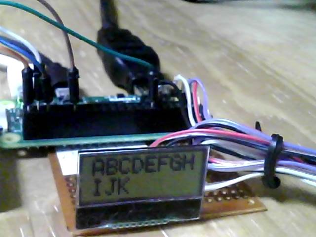
次のようにすれば表示します。
制御コマンドで表示位置(LCD表示位置アドレス)を2行目1桁に設定します。
-------------------------------------------------
bus.write_byte_data(add_lcd, write_set, 0x41) #A
bus.write_byte_data(add_lcd, write_set, 0x42) #B
bus.write_byte_data(add_lcd, write_set, 0x43) #C
bus.write_byte_data(add_lcd, write_set, 0x44) #D
bus.write_byte_data(add_lcd, write_set, 0x45) #E
bus.write_byte_data(add_lcd, write_set, 0x46) #F
bus.write_byte_data(add_lcd, write_set, 0x47) #G
bus.write_byte_data(add_lcd, write_set, 0x48) #H
bus.write_byte_data(add_lcd, control_set, 0xc0)#表示位置2行1桁目
bus.write_byte_data(add_lcd, write_set, 0x49) #I
bus.write_byte_data(add_lcd, write_set, 0x4a) #J
bus.write_byte_data(add_lcd, write_set, 0x4b) #K
-------------------------------------------------
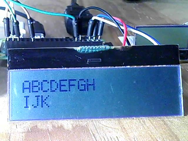
ABCDEFGHIJKの表示
LCDの文字表示は、最初にLCDの初期化をした後、表示文字をASCコードに変換したデータをLCDに書き込みます。
例えば、"A"なら0x41、LCD資料のキャラクターパターン参照(0x00-0xFF)
<LCDの初期化 データーシートから>
①Functionset(0x38)
>27μs待つ
↓
②Functionset(0x39)
>27μs待つ
↓
③Internal OSC frequency(0x14)
>27μs待つ
↓
④Contrastset(0x70)
>27μs待つ
↓
⑤Power/ICON/Contrastcontrol(0x56)
>27μs待つ
↓
⑥Follower control(0x6c)
>200ms待つ
↓
⑦Functionset(0x39)
>27μs待つ
↓
⑧Clear Display(0x01)
>27μs待つ
↓
⑨Clear Display ON/OFF control(0x0c)
>27μs待つ
<python3でAを表示するプログラムの基本>
-----------------------------------------------------------
import smbus
from time import sleep
#*****lcd初期化*****
smbus.SMBus(1).write_byte_data(0x3e, 0x00, 0x38) #①
sleep(0.0001)
smbus.SMBus(1).write_byte_data(0x3e, 0x00, 0x39) #②
sleep(0.0001)
smbus.SMBus(1).write_byte_data(0x3e, 0x00, 0x14) #③
sleep(0.0001)
smbus.SMBus(1).write_byte_data(0x3e, 0x00, 0x70) #④
sleep(0.0001)
smbus.SMBus(1).write_byte_data(0x3e, 0x00, 0x56) #⑤
sleep(0.0001)
smbus.SMBus(1).write_byte_data(0x3e, 0x00, 0x6c) #⑥
sleep(0.2)
smbus.SMBus(1).write_byte_data(0x3e, 0x00, 0x38) #⑦
sleep(0.0001)
smbus.SMBus(1).write_byte_data(0x3e, 0x00, 0x0c) #⑧
sleep(0.0001)
smbus.SMBus(1).write_byte_data(0x3e, 0x00, 0x01) #⑨
sleep(0.0001)
sleep(1) #lcd初期化 確認のため1sだが、もっと速く0.0001でもOK
smbus.SMBus(1).write_byte_data(0x3e, 0x40, 0x41) #A の表示
-----------------------------------------------------------
少し発展させたABCDEFGH表示のプログラム
-------------------------------------------------
import smbus
from time import sleep
bus = smbus.SMBus(1)
add_lcd = 0x3e
control_set = 0x00
write_set = 0x40
#*****lcd初期化*****
bus.write_byte_data(add_lcd, control_set, 0x38)
sleep(0.0001)
bus.write_byte_data(add_lcd, control_set, 0x39)
sleep(0.0001)
bus.write_byte_data(add_lcd, control_set, 0x14)
sleep(0.0001)
bus.write_byte_data(add_lcd, control_set, 0x70)
sleep(0.0001)
bus.write_byte_data(add_lcd, control_set, 0x56)
sleep(0.0001)
bus.write_byte_data(add_lcd, control_set, 0x6c)
sleep(0.2)
bus.write_byte_data(add_lcd, control_set, 0x38)
sleep(0.0001)
bus.write_byte_data(add_lcd, control_set, 0x0c)
sleep(0.0001)
bus.write_byte_data(add_lcd, control_set, 0x01)
sleep(0.0001)
sleep(1) #lcd初期化 確認のため1sだが、もっと速くして0.0001でもOK
#*****ABCDEFGHの表示*****
bus.write_byte_data(add_lcd, write_set, 0x41) #A
bus.write_byte_data(add_lcd, write_set, 0x42) #B
bus.write_byte_data(add_lcd, write_set, 0x43) #C
bus.write_byte_data(add_lcd, write_set, 0x44) #D
bus.write_byte_data(add_lcd, write_set, 0x45) #E
bus.write_byte_data(add_lcd, write_set, 0x46) #F
bus.write_byte_data(add_lcd, write_set, 0x47) #G
bus.write_byte_data(add_lcd, write_set, 0x48) #H
-------------------------------------------------
ABCDEFGHに続いて、IJKを表示させるため下のようにしましたが表示しません。
-------------------------------------------------
bus.write_byte_data(add_lcd, write_set, 0x41) #A
bus.write_byte_data(add_lcd, write_set, 0x42) #B
bus.write_byte_data(add_lcd, write_set, 0x43) #C
bus.write_byte_data(add_lcd, write_set, 0x44) #D
bus.write_byte_data(add_lcd, write_set, 0x45) #E
bus.write_byte_data(add_lcd, write_set, 0x46) #F
bus.write_byte_data(add_lcd, write_set, 0x47) #G
bus.write_byte_data(add_lcd, write_set, 0x48) #H
bus.write_byte_data(add_lcd, write_set, 0x49) #I
bus.write_byte_data(add_lcd, write_set, 0x4a) #J
bus.write_byte_data(add_lcd, write_set, 0x4b) #K
-------------------------------------------------
次のようにすれば表示します。
制御コマンドで表示位置(LCD表示位置アドレス)を2行目1桁に設定します。
-------------------------------------------------
bus.write_byte_data(add_lcd, write_set, 0x41) #A
bus.write_byte_data(add_lcd, write_set, 0x42) #B
bus.write_byte_data(add_lcd, write_set, 0x43) #C
bus.write_byte_data(add_lcd, write_set, 0x44) #D
bus.write_byte_data(add_lcd, write_set, 0x45) #E
bus.write_byte_data(add_lcd, write_set, 0x46) #F
bus.write_byte_data(add_lcd, write_set, 0x47) #G
bus.write_byte_data(add_lcd, write_set, 0x48) #H
bus.write_byte_data(add_lcd, control_set, 0xc0)#表示位置2行1桁目
bus.write_byte_data(add_lcd, write_set, 0x49) #I
bus.write_byte_data(add_lcd, write_set, 0x4a) #J
bus.write_byte_data(add_lcd, write_set, 0x4b) #K
-------------------------------------------------
ABCDEFGHIJKの表示
 次にLCDのDisplay ON/OFFの制御コマンドを使うと表示のON/OFFが出来ます。
while Trueの中の#Display ON/OFF部分
-------------------------------------------------
bus.write_byte_data(add_lcd, write_set, 0x41) #A
bus.write_byte_data(add_lcd, write_set, 0x42) #B
bus.write_byte_data(add_lcd, write_set, 0x43) #C
bus.write_byte_data(add_lcd, write_set, 0x44) #D
bus.write_byte_data(add_lcd, write_set, 0x45) #E
bus.write_byte_data(add_lcd, write_set, 0x46) #F
bus.write_byte_data(add_lcd, write_set, 0x47) #G
bus.write_byte_data(add_lcd, write_set, 0x48) #H
bus.write_byte_data(add_lcd, control_set, 0xc0)#表示位置2行1桁目
bus.write_byte_data(add_lcd, write_set, 0x49) #I
bus.write_byte_data(add_lcd, write_set, 0x4a) #J
bus.write_byte_data(add_lcd, write_set, 0x4b) #K
while True:
sleep(1)
bus.write_byte_data(add_lcd, control_set, 0x08) #Display ON/OFF (OFF)
sleep(1)
bus.write_byte_data(add_lcd, control_set, 0x0c) #Display ON/OFF (ON)
-------------------------------------------------
以上、AQM0802を使用した基本的部分のプログラムでした。
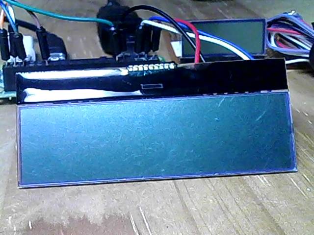
<AQM1602>
次に、AQM1602(16文字/1行 2行)の文字表示ですが、AQM0802と同じように
RraspberryPiと接続しましたが、動きませんでした。
次にLCDのDisplay ON/OFFの制御コマンドを使うと表示のON/OFFが出来ます。
while Trueの中の#Display ON/OFF部分
-------------------------------------------------
bus.write_byte_data(add_lcd, write_set, 0x41) #A
bus.write_byte_data(add_lcd, write_set, 0x42) #B
bus.write_byte_data(add_lcd, write_set, 0x43) #C
bus.write_byte_data(add_lcd, write_set, 0x44) #D
bus.write_byte_data(add_lcd, write_set, 0x45) #E
bus.write_byte_data(add_lcd, write_set, 0x46) #F
bus.write_byte_data(add_lcd, write_set, 0x47) #G
bus.write_byte_data(add_lcd, write_set, 0x48) #H
bus.write_byte_data(add_lcd, control_set, 0xc0)#表示位置2行1桁目
bus.write_byte_data(add_lcd, write_set, 0x49) #I
bus.write_byte_data(add_lcd, write_set, 0x4a) #J
bus.write_byte_data(add_lcd, write_set, 0x4b) #K
while True:
sleep(1)
bus.write_byte_data(add_lcd, control_set, 0x08) #Display ON/OFF (OFF)
sleep(1)
bus.write_byte_data(add_lcd, control_set, 0x0c) #Display ON/OFF (ON)
-------------------------------------------------
以上、AQM0802を使用した基本的部分のプログラムでした。
<AQM1602>
次に、AQM1602(16文字/1行 2行)の文字表示ですが、AQM0802と同じように
RraspberryPiと接続しましたが、動きませんでした。
 原因を調べるため、まずターミナルからi2cdetect -y 1でアドレスを
確認すると、このアドレス値(3e)が出たり出なかったりします。
原因を調べるため、まずターミナルからi2cdetect -y 1でアドレスを
確認すると、このアドレス値(3e)が出たり出なかったりします。
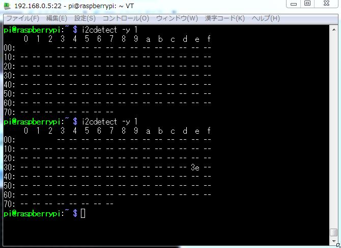 考えられる原因に、AQM1602がI2Cバスの電流を引き込むことが出来ないと正常動作しないとあります。
AQM0802は、大丈夫でしたので・・・(ーー;)
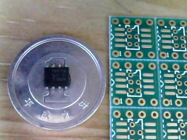
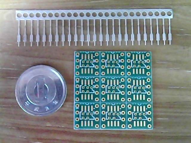
このAQM1602を購入するとき、万が一を考えてバッファのPCA9515ADと基板とピンを購入していました。
PCA9515ADと基板 基板とピン
考えられる原因に、AQM1602がI2Cバスの電流を引き込むことが出来ないと正常動作しないとあります。
AQM0802は、大丈夫でしたので・・・(ーー;)
このAQM1602を購入するとき、万が一を考えてバッファのPCA9515ADと基板とピンを購入していました。
PCA9515ADと基板 基板とピン
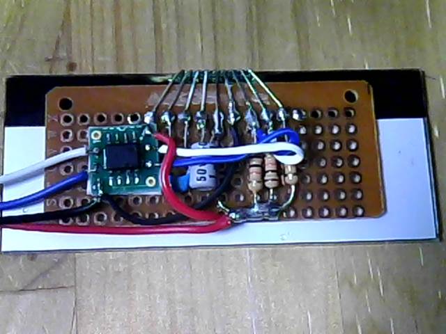
 早々、このPCA9515ADを取り付けたところ問題なく動きました。
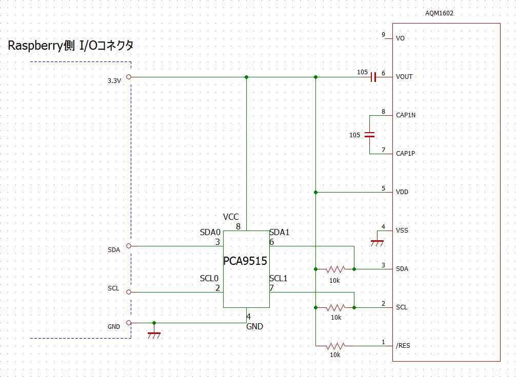
 回路図
回路図
 先ほどのABCDEFGHIJKの表示がON/OFFするプログラムをそのまま走らせました。
問題なく、動きました。(ABCDEFGHが1行目の8桁まで、IJKは2行目の3桁まで)
先ほどのABCDEFGHIJKの表示がON/OFFするプログラムをそのまま走らせました。
問題なく、動きました。(ABCDEFGHが1行目の8桁まで、IJKは2行目の3桁まで)
 制御コマンドを、もっと使うと更に動きある表示が楽しめると思います。
 Raspberry Pi-45に続く・・・
Raspberry メニューに戻る
Raspberry Pi-45に続く・・・
Raspberry メニューに戻る